If you want to control luminaires with occupancy and daylight sensors, you need dimmable LED drivers, and you need to know which dimming interface they have. The common variants are 1–10 V, 0–10 V, DALI and PWM, and there is also the question of whether the driver can switch off completely via the control signal (dim-to-off). This guide explains the differences, shows what to look for in a driver and sets out which luminaires work with our sensors according to the data sheets.
Why the dimming interface decides what lighting control can do
Networked lighting control saves the most energy when it does more than switch light on and off and instead adjusts it continuously: topping up daylight, dimming to a background light when nobody is present, calling up scenes. To do this, the sensor or controller has to be able to tell the LED driver how bright the luminaire should be. That is exactly what the dimming interface does. If the driver is not dimmable, switching is the only option, and a large part of the potential stays unused. Our guide to daylight harvesting describes how daylight control works in detail.
The interfaces at a glance
1–10 V
The 1–10 V interface is an analogue standard that has been widespread for decades. The driver provides a voltage on the pair of control wires and the control device pulls it down: at 10 V the luminaire is at full brightness, at 1 V at the minimum dimming level. Below 1 V, a conventional 1–10 V driver does not switch off but stays at minimum. To switch off, a relay in the mains circuit is therefore usually needed. If the control cable is interrupted, the driver typically goes to full brightness, a behaviour that provides light in the event of a fault.
0–10 V
0–10 V also refers to analogue DC voltage control. However, the terms are not used consistently on the market: some manufacturers mean the same principle as 1–10 V, others a driver that uses the range down to 0 V and switches off completely at very low control voltages. So check in the data sheet who supplies the control voltage (driver or control device), what happens below 1 V and whether the driver supports dim-to-off.
DALI
DALI (Digital Addressable Lighting Interface) is a digital, bidirectional two-wire bus, standardised internationally in the IEC 62386 series. On a DALI line, up to 64 control gear devices can be individually addressed and combined into up to 16 groups. The devices can report status and faults, and with DALI-2 and D4i also operating and energy data. A DALI line needs its own bus supply and a control cable to every luminaire. The bus is polarity-free, and addressing takes place during commissioning.
PWM
With pulse width modulation, the LED is switched on and off in rapid succession; the ratio of on-time to off-time determines the perceived brightness. PWM is mainly used as an output from control modules inside a luminaire. A sufficiently high frequency is important to prevent visible flicker.
| Feature | 1–10 V | 0–10 V | DALI |
|---|---|---|---|
| Signal | analogue | analogue | digital |
| Direction | command only | command only | bidirectional, with feedback |
| Addressing | via wiring | via wiring | each device individually, groups and scenes |
| Switching off | usually via relay | depending on driver, via signal (dim-to-off) or relay | via command |
| Additional cable | pair of control wires | pair of control wires | bus cable to the luminaire |
| Typical use | existing buildings, simple groups | luminaires with integrated control | centrally planned installations, new build |
Dim-to-off and auxiliary voltage: the underrated details
Dim-to-off means that the driver switches the LEDs off via the control signal but stays connected to the mains in a standby state. This is central to lighting control at luminaire level. If the sensor sits in or on the luminaire, it must keep its power supply even when the light is off. Otherwise it could no longer detect occupancy or switch the luminaire back on.
Many modern drivers provide an auxiliary output (AUX) with 12 V DC for this purpose. It powers the sensor or wireless module without a separate power supply unit. This is exactly the principle our luminaire sensors are built on. You can read more about the concept in our guide to luminaire-level lighting control (LLLC).
What to look for in a driver
Whether a luminaire is easy to control is decided in the driver. Clarify these points before ordering or retrofitting:
- Interface: 1–10 V, 0–10 V, DALI or PWM, and does it match the planned sensor or controller?
- Dimming range: how far down can the driver dim? A wide dimming range allows a pleasant background light and fine daylight control.
- Dim-to-off: does the driver switch off via the signal, or is a relay needed?
- Auxiliary voltage: is there a 12 V DC output, and is its load capacity sufficient for the intended sensor?
- Dimming curve and flicker behaviour: does dimming look even, and does the light stay flicker-free at low levels?
- Standby consumption: in the dim-to-off state, the driver still draws a small amount of power; the value is in the data sheet.
- Mechanics: is there space and a suitable opening in the luminaire for the sensor, and does the connection socket fit?
Which luminaires work with our sensors
The following information comes from the data sheets of our components. It shows which requirements the luminaire has to meet.
| Component | Power supply per data sheet | Connection to the luminaire | Mounting height / use |
|---|---|---|---|
| IFS105SE | 12 V DC | connecting cable from sensor to driver | up to approx. 5.5 m, offices, corridors, classrooms |
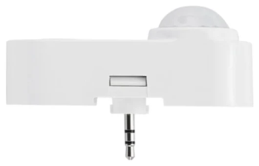
| IFS108 | 12 V DC via AUX interface | 2.5 mm connection socket (SC05) | up to approx. 6 m, compact for office luminaires |
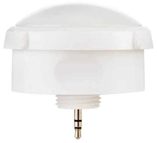
| EFS106 | 12 V DC via the driver's AUX interface | 3.5 mm connection socket (SC01) | 6–12 m, halls and warehouses |
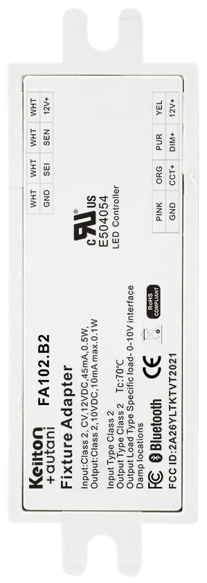
| FA102 | 12 V DC from the auxiliary output of dimmable LED drivers (dim-to-off) | output 0–10 V, dual 0–10 V or PWM depending on variant | installation in luminaires, retrofit, with Eco sensors such as the MWS105E |
| EFS104 | 120–277 V AC, integrated power supply | sensor and controller in one, switches up to 1,400 W | 6 to 15 m, with HBL3-2 lens |
This gives a simple rule of thumb: for the Keilton+autani luminaire sensors you need a dimmable LED driver with a 12 V auxiliary output, and for the FA102 you also need dim-to-off and a 0–10 V or PWM input. A driver that only understands DALI does not work with the FA102; for DALI luminaires, we match sensors with a DALI connection to your drivers. Conventional 1–10 V drivers should be checked individually, because switch-off behaviour and signal direction can differ. The sensor finder shows which sensor suits your situation.
All sensors communicate with each other via Bluetooth Mesh, so no additional control cables are needed between the luminaires. Via the AU-Manager they provide occupancy detection, zoning and monitoring.
Retrofit: what is possible with existing luminaires
In existing buildings, there are usually three starting points:
- LED luminaires with a dimmable driver and 12 V auxiliary output: here, a sensor or the FA102 Bluetooth node can often be added directly in or on the luminaire.
- LED luminaires with a non-dimmable driver: either the driver is replaced with a dimmable model, or the luminaire is replaced. Alternatively, in halls, a mains-powered sensor such as the EFS104 can do the switching, though without continuous dimming.
- Conventional luminaires with fluorescent or discharge lamps: here it is generally worth converting to LED, and adding sensors at the same time. Our guide to LED retrofit with sensors explains why the two belong together.
Anyone altering luminaires should keep the warranty and the luminaire's conformity in mind. For larger quantities, it makes sense to coordinate the integration with the luminaire manufacturer or to choose luminaires with a factory-prepared sensor socket. Our guide to retrofitting lighting controls gives an overview of the options for existing buildings, and you will find a comparison of the system approaches under DALI or Bluetooth Mesh?.
Dimming in everyday use: background light, daylight, scenes
With a dimmable driver, an occupancy sensor becomes a tool for comfort and efficiency. Typical functions are a dimmed background light in corridors and halls when nobody is there, topping up daylight at window seats, and scenes via a wall switch such as the WP108E with DIM+/DIM− buttons. Our guide to background light and the corridor function explains how dimming instead of switching off increases acceptance. You can estimate how much your building could save with the savings calculator.
How we can help
Our focus is retrofitting: we turn existing LED luminaires with dimmable 0-10 V or DALI drivers into intelligent lighting using sensors and app-based lighting management, with no new luminaires and no new control cabling. Details are on our retrofit page.
We survey your building on site, check luminaires and drivers and plan which sensors make sense in which luminaire. In our 3D software Sensora, you can experience the lighting control in advance. We usually handle the installation ourselves, or your own electrical contractor can do it if you prefer; monitoring via the AU-Manager is included. Get in touch via our contact page.
Try it interactively
Sensor finder
Frequently asked questions
What is the difference between 1–10 V and 0–10 V?
Both are analogue DC voltage dimming interfaces. A conventional 1–10 V driver dims to a minimum value and does not switch off below 1 V, so a relay is usually needed. Manufacturers use the term 0–10 V partly for the same principle and partly for drivers that switch off at very low control voltages. The data sheet is what counts.
What does dim-to-off mean for LED drivers?
Dim-to-off means that the driver switches the LEDs off via the control signal but stays connected to the mains. A sensor in the luminaire can then keep drawing power from the driver's auxiliary voltage and switch the luminaire back on when someone is present.
Is DALI better than 0–10 V?
DALI is digital and bidirectional and allows individual control gear devices to be addressed with feedback. 0–10 V is simpler and cheaper to implement, but provides no feedback. Which interface fits better depends on the system concept: with wireless lighting control at luminaire level, the network takes on many of the tasks otherwise handled by DALI.
Which drivers do I need for Building Robotics sensors?
According to their data sheets, the Keilton+autani luminaire sensors IFS105SE, IFS108 and EFS106 are powered with 12 V DC from the driver. The FA102 Bluetooth node needs a dimmable LED driver with a 12 V auxiliary output and dim-to-off, and dims via 0–10 V or PWM.
Can I retrofit existing LED luminaires with sensors?
Yes, if the driver is dimmable and provides a suitable auxiliary voltage. If it is not dimmable, the driver is replaced or the luminaire is replaced. In halls, a mains-powered high bay sensor such as the EFS104 can also switch without any change to the driver.